


In injection molding, the generation of stress marks (light marks/bone shadows) is the result of the combined effects of multiple factors such as materials, structures, molds and processes. The following systematic analysis from technical principles to solutions can help engineers accurately locate problems and optimize production:

1. The core mechanism of stress mark formation The essence of internal stress
Flow orientation stress: Molecular chain orientation during melt flow, residual stress is formed due to shrinkage differences after cooling and solidification.
Uneven thermal shrinkage: The cooling rates of different wall thickness areas are different, and the rapid cooling of the outer layer produces tensile stress on the inside.
Mechanical constraint stress: Mechanical constraints such as ejection systems and inserts hinder free shrinkage, resulting in local stress concentration.
Stress release performance
Molecular chains in high stress areas are rearranged, and microcracks or refractive index changes (white and shiny) appear on the surface.
Influence of material properties: Stress marks are more significant in high modulus materials such as PC, and PP is prone to cracking at the junction of thick and thin due to its high crystallinity.
II. In-depth analysis of key factors and countermeasures
(I) Product structure design optimization
Wall thickness uniformity design
Problem: Sudden change in wall thickness (such as a sudden decrease from 3mm to 1mm) leads to differences in melt front flow velocity and insufficient shrinkage compensation during the holding stage.
Countermeasures:
Use gradual transition (taper ≥1:3) to avoid right-angle steps.
Add crater structure or glue removal treatment in thick-walled areas (Figure 1).
Rib thickness ≤ 60% of the main wall thickness, root R angle ≥ 0.5T.
Topology optimization of stress-sensitive areas
Use CAE software (such as Moldflow) to perform filling-holding-cooling coupling analysis to predict stress concentration areas.
Chamfer the ejector pin and insert periphery (R ≥ 0.3mm) to reduce sharp corner stress.
(II) Mold system improvement plan
Refined design of pouring system
Gate type selection:
The latent gate can reduce the stress in the gate area (applicable to ABS/PP).
For high viscosity materials such as PC, fan-shaped gates are preferred to reduce shear stress.
Gate position verification:
The mold flow analysis verifies that the gate is far away from the thick-thin junction area to avoid the superposition of weld lines and stress marks.
Ejector system optimization
Ejector pin layout: Increase the ejector pin density in the stress mark area (spacing ≤50mm), and use ejectors with a diameter of φ3mm or more.
Ejector timing control: Use nitrogen springs to delay ejection to ensure that the product is fully cooled (the ejection temperature of PC materials needs to be <100℃).
Efficient design of cooling system
Conformal cooling water channel: Arrange spiral water channels in the stress mark area to ensure that the cooling rate difference is <15%.
Zoned temperature control: Independent temperature control of thick-walled area and thin-walled area, such as increasing the mold temperature of thick-walled area of PP products to 60℃. (III) Precise control of process parameters
Press holding curve optimization
Segmented press holding control:
Stage 1: 90% injection pressure for 2s to compensate for shrinkage.
Stage 2: Linear pressure reduction to 30% pressure for 5s to promote molecular chain relaxation.
Press holding switching point: Determine the optimal switching point through VP-HP switching experiment (usually 95%~98% filling volume).
Temperature field coordinated control
Melt temperature: ABS recommends 220~240℃, PC requires 280~310℃ to avoid high shear stress caused by low temperature.
Mold temperature gradient: For PP products, the mold temperature of the thin-walled area is 40℃, and the thick-walled area is 60℃ to reduce cooling differences.
Stress relaxation process
For high-stress materials such as PC, in-mold annealing is used: maintain the mold temperature (100℃) for 30s after the press holding is completed.
Post-treatment: 80℃ oven annealing for 2h (ABS), which can eliminate 30%~50% residual stress.
III. Material selection and modification suggestions Base material selection High fluidity grades are preferred (such as ABS PA-757, melt index 25g/10min), reducing the need for holding pressure.
Low shrinkage modified materials are selected (such as PP+20% talcum powder, shrinkage rate is reduced from 1.8% to 0.8%).
Additive application 0.5%~1% styrene-butadiene block copolymer (SBS) is added to improve the compatibility of PC/ABS system.
Nano calcium carbonate filling (3%~5%) can evenly disperse stress and reduce the generation of silver streaks.
IV. Quality monitoring system Online detection technology Use infrared thermal imager to monitor the temperature distribution at the moment of ejection. If the temperature difference is greater than 15℃, cooling needs to be adjusted.
Polarized light stress meter is used for quantitative detection. Residual stress greater than 12MPa is determined as a high-risk area.
Failure Analysis Process
Slice the defective parts for observation (metallographic microscope), DSC analysis (difference in crystallinity), and XRD detection of orientation.
Establish stress mark grade standards (0~5 levels) to guide process window optimization.
V. Typical Case Reference
Case 1: Bone shadow problem of a certain automobile PP instrument panel
Root cause: Insufficient R angle at the root of the reinforcing rib (0.2mm) + excessive ejector spacing (80mm).
Countermeasure: The R angle was increased to 0.8mm, 4 φ4mm ejectors were added, the mold temperature was increased to 55℃, and the defect rate dropped from 12% to 0.3%.
Case 2: Whitening of PC mobile phone shell gate stress
Root cause: The point gate diameter was too small (φ0.8mm), resulting in a shear rate exceeding 40000s⁻¹.
Countermeasure: Change to φ1.2mm fan gate, the melt temperature was raised to 300℃, the holding pressure was reduced by 20%, and the defect was eliminated.
Through systematic design specifications, mold innovation, process digitization and material science application, the stress mark defect rate can be effectively controlled below 0.5%, significantly improving product yield and market competitiveness.
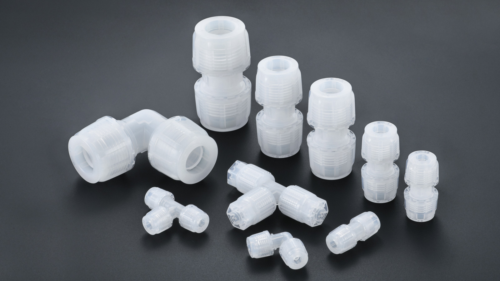
Yize Mould focuses on precision injection mold, medical injection molding and plastic injection molding, producing high-quality precision parts and Teflon tube fittings, suitable for high-precision requirements, semiconductors, and medical product fields.